
 Email: sales@slxytech.com
 WhatsApp / Wechat:8617062388866
 Phone:+86 17062388866
Description
| Product Model | CMU 42015-115-00 |
| Manufacturer | ALSTOM (GE Steam Power legacy) |
| Product Category | Central Monitor Unit (Vibration Processing) |
| Compatible System | Speedtronic™ Mark IV Turbine Control |
| Input Channels | 8 dynamic signal channels |
| Signal Types | IEPE accelerometers, velocity transducers, dynamic pressure |
| Frequency Range | 0.5 Hz to 20 kHz (±1dB) |
| Sampling Rate | 25.6 kS/s per channel |
| Resolution | 24-bit ADC with 100dB dynamic range |
| Alarm Outputs | 8 programmable relay (trip/alarm) |
| Communication | RS-232/RS-485, IEEE 488 (GPIB) |
| Power Supply | 115VAC ±10% / 50-60Hz |
| Operating Temperature | -30°C to +65°C (-22°F to +149°F) |
| Certifications | UL 508, MIL-STD-202G vibration |
Product Introduction
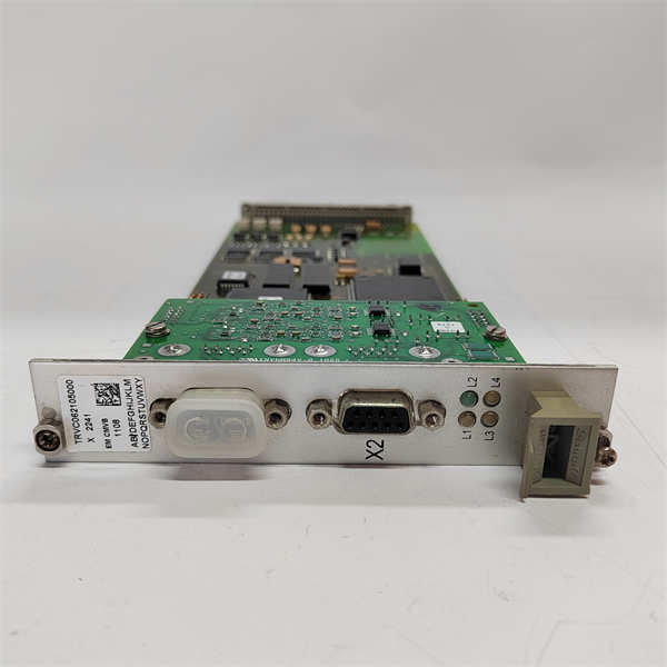
The ALSTOM CMU 42015-115-00 is a high-density vibration monitoring and protection unit designed for critical rotating machinery in Speedtronic™ Mark IV turbine control systems. Serving as the Central Monitor Unit (CMU), this specialized module performs real-time signal processing for up to eight dynamic measurement channels, converting raw vibration and pressure data into actionable machinery health intelligence.
Engineered for power generation applications, the CMU 42015-115-00 integrates dual DSP processors that simultaneously execute protection logic (API 670 compliant) and condition monitoring functions. Its core value lies in preventing catastrophic failures through millisecond-response trip decisions while providing detailed spectral data for predictive maintenance. The module interfaces directly with turbine control relays and external systems like Bently Nevada™ 3500 or GE System 1™ via multiple industrial protocols. For combined-cycle plants and industrial turbines, the ALSTOM CMU 42015-115-00 delivers uncompromised reliability with MIL-STD-202G certified resistance to 7g vibration and 50g shock loads.
ALSTOM CMU 42015-115-00
Core Advantages and Technical Highlights
Dual-layer processing architecture: The CMU 42015-115-00 implements separate protection and monitoring signal paths. Hardware-based overspeed/trip circuits (SIL 2) operate independently from digital condition monitoring DSPs, ensuring failsafe shutdown even during processor faults.
Advanced diagnostics: Onboard algorithms perform real-time:
Order tracking for blade resonance detection
Orbit analysis for bearing wear
Peak-hold waveform capture for transient events
Automatic sensor validation (ASV)
Multi-protocol integration: Simultaneous RS-485 Modbus streaming (for SCADA) and IEEE 488 GPIB output (for diagnostic workstations). Built-in data buffering prevents loss during network congestion.
Extreme environment resilience: Conformal-coated PCBs withstand 98% humidity. Stainless steel chassis dissipates heat in turbine enclosures. Channel-to-channel isolation >500V prevents ground loops.
Typical Application Scenarios
Gas turbine protection: Monitors combustor dynamics pressure at 2kHz sampling to detect flame instability. Triggers<100ms>
Steam turbine supervisory system: Tracks bearing cap vibration during critical speed transitions. The CMU 42015-115-00‘s order analysis identifies misalignment-induced 2X harmonics before seal rub occurs.
Compressor station safeguarding: Processes reciprocating compressor rod load data via strain gauges. Relays trigger shutdown on detecting abnormal cylinder pressure waveforms indicating valve failure.
Hydroelectric condition monitoring: Analyzes generator stator core vibration during load rejection. Water ingress detection via low-frequency (<5hz>
Related Model Recommendations
CMU 42015-115-00 VER.A01: Enhanced EMI shielding revision
TVQB-1: Quad-bearing monitor (front-end interface)
TREG-3: Turbine regulator controller
TDZE-2: Proximitor power supply
IS200VPROH1C: GE Mark VIe equivalent processor
3500/42M: Bently Nevada vibration monitor
9200-01-02-10-00: Replacement signal conditioner
TK3-2E: Terminal board assembly
ALSTOM CMU 42015-115-00
Installation, Commissioning and Maintenance Instructions
Installation preparation: Secure mounting in VTCC rack with M6 shock-resistant hardware. Maintain 50mm clearance for airflow. Verify clean earth ground (<0>
Commissioning procedure: Perform sensor phasing with portable calibrator. Set alarm thresholds at 125% of normal operating levels. Validate trip circuits by signal injection at 110% trip point. Configure GPIB address switches (SW1-SW8).
Maintenance suggestions: Quarterly verification of relay contact resistance (<50m>
Green:<60>
Amber: 60-85% (consider optimization)
Red: >85% (immediate action required)
<!--60--><!--50m--><!--0--><!--5hz--><!--100ms-->